Apex Balloons designs, builds, maintains and operates hot air airships for advertising, scientific research, aerial photography, recreation, surveying & observation, and other uses. A hot air airship may be the ideal platform for applications requiring low-level station-keeping and minimal environmental disturbance. While a helicopter can hover and maintain position above a target point, the downwash from the rotor blades is highly disturbing at low altitudes. Airplanes, powered parachutes, and other aerodynamic aircraft fly far too quickly to be of use for stationary or slow-speed operations. Helium blimps have a narrow weight range to maintain, cannot carry heavy payloads without awkward ballasting and re-ballasting, and must maintain a forward airspeed to generate enough dynamic lift to remain airborne when flying "heavy." The most notable such use of a hot air airship yet has been a campaign of rainforest canopy research involving an underslung inflated raft. Significant payloads can be carried with larger hot air airships, as the propane burners can rapidly generate extra lift to carry large payloads at a moment's notice.
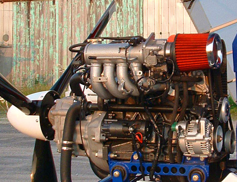
Although we currently operate other makes of airships, we are in the early stages of developing our own advanced, pressurized, streamlined hot air airship which will eventually undergo standard Type Certification under FAA regulations. The certification process will take a number of years, but it is a necessary and grueling procedure for any aircraft which will be used in commercial flight operations. Propulsion and fin pressure for the prototype airship will be provided by a 1.3L, 80HP fuel injected, four-cylinder, liquid-cooled Geo/Suzuki G13B engine coupled with a custom planetary gear propeller speed reduction unit (PSRU). The 1.3L Geo/Suzuki has an equivalent power-to-weight ratio of the Rotax 503, a common two-stroke engine found in hot air airships and ultralight aircraft. While the 1.3L engine is heavier, it is also proportionally more powerful, but still manages to go through less than half the fuel that a comparably-powered two-stroke burns.
Reasons for choosing the four-stroke Geo/Suzuki G13 automobile engine rather than a purpose-built two-stroke ultralight aircraft engine:
Specific reasons for not choosing a two-stroke ultralight engine:
A three-bladed 65"-diameter ground-adjustable composite propeller has been selected for use on the prototype airship. A propeller shroud/duct is a possibility, to simultaneously lessen propeller noise while increasing thrust. A pair of optional manually-operated clamshell thrust reversers can act as air brakes - sometimes necessary when landing or maneuvering at low speeds in still air. A unique design feature of the envelope is an internal system of inflatable fabric battens pressurized by the propulsion slipstream. These stiffeners are a relatively simple solution which will make the nose less likely to cave in at higher airspeeds, a problem all current hot air airships face to some degree (with the exception of Dan Nachbar's semi-rigid Personal Blimp). This system of pressure tubes also inflates the tail fins and rudder in the same manner. When the propulsion motor is turned off, one-way fabric check valves in the nose and tail hemispheres keep air from rushing back out of the fins and battens.
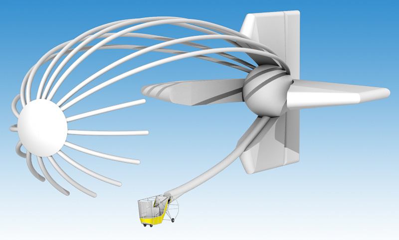
Pressurization system overview We're considering experimenting with a separate internal tube system (not shown) which would have its own dedicated inlet at the air scoop behind the gondola. The air tube connected to this inlet will continue through the rear fin hemisphere and then branch off inside of the rudder to multiple rear-facing air exits spread evenly up the height of the rudder. These "jets" will direct propwash in line with the rudder's direction and should conceivably help increase slow-speed maneuvering with the engine at low or idle. The jets will be of slightly smaller diameter than the tubes to maintain positive internal tube pressure. The main envelope will be fed fresh air for combustion by an electric fan running off of the engine's electrical system. This fan provides a constant supply of fresh air to the burners and helps provide some of the pressure necessary for the airship envelope to maintain its proper shape. The scoop behind the propeller provides the majority of pressurization force, and thus the pressure is a function of propulsion engine throttle. This means higher pressure is available when operating at higher airspeeds. Two fabric overpressure valves will be located at the bottom of the envelope, one fore and one aft of the gondola. The lowest point in the envelope is where exhaust gases from combustion settle, and these two overpressure vents are designed to expel this exhaust air in conjunction with the electric fan underneath the burners. This removes the possibility of burner pilot light flameouts due to oxygen deprivation. An internal fabric bulkhead allows for pitch control using the two opposing fore and aft burners. This bulkhead also limits the internal air movement ("sloshing"), a problem witnessed in more than a couple early streamlined hot air airships. |

All content and images copyright ©2000- Jon Radowski unless otherwise noted. All rights reserved.